A tiny computer.
Nothing you don't need.
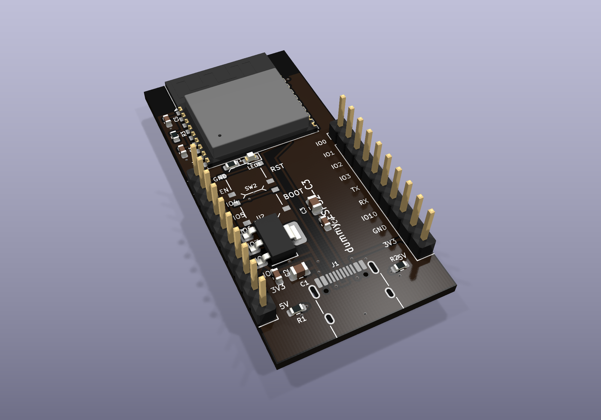
dummy is a minimal ESP32-C3 dev board: 18 parts, USB-C, WiFi and Bluetooth. Plug it in and it does what you say. No drivers. No setup. No mystery.
Specs
Everything on the board earns its place. Here's what you get.
CPUESP32-C3-WROOM-02-N4
Single-core RISC-V at 160 MHz, 400 KB RAM, 4 MB flash. The same chip family found in millions of smart-home devices.
RADIOWiFi + Bluetooth LE 5.0
2.4 GHz WiFi (join a network or broadcast your own) and BLE. The antenna overhangs the board edge on purpose — clear signal.
USBUSB-C, wired straight to the chip
No USB-serial translator chip. Power, programming, and serial debug over one cable. Shows up the moment you plug it in.
POWER5 V in, 3.3 V logic
AMS1117 regulator on board. Feed it from USB, a power bank, or the 5V pin. Code lives in flash and runs on any power source.
IO15 GPIO on 20 labelled pins
Two 10-pin headers, every pin labelled on the silkscreen. ADC, I2C, SPI, UART, PWM — sensors, motors, lights.
SAFEUn-brickable by design
RESET restarts the board. Hold BOOT while plugging in and the chip waits quietly for new code - recovery is always possible.
The board
Matte black, machine-assembled, every part placed by robots.
Pinout
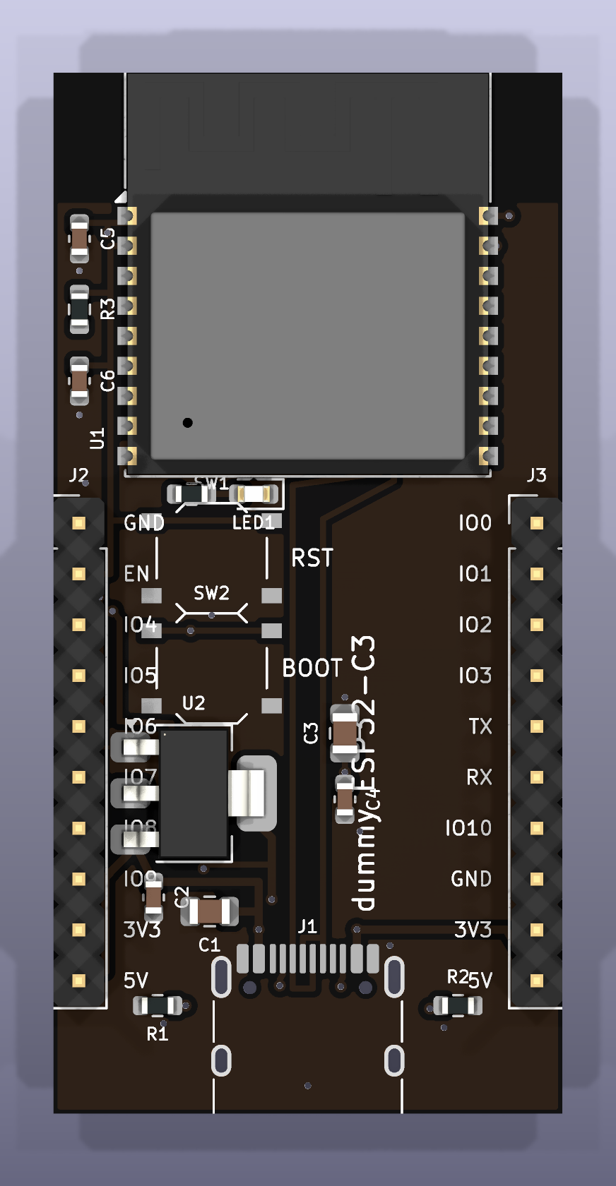
Ten pins a side. Also printed on the board itself, because nobody remembers.
| GND | ground |
| EN | enable / reset |
| IO4 | gpio · adc |
| IO5 | gpio · adc |
| IO6 | gpio |
| IO7 | gpio |
| IO8 | gpio · blue LED |
| IO9 | gpio · BOOT |
| 3V3 | 3.3 V out |
| 5V | 5 V in/out |
| IO0 | gpio · adc |
| IO1 | gpio · adc |
| IO2 | gpio · adc |
| IO3 | gpio · adc |
| TX | uart tx · IO21 |
| RX | uart rx · IO20 |
| IO10 | gpio |
| GND | ground |
| 3V3 | 3.3 V out |
| 5V | 5 V in/out |
Under the hood
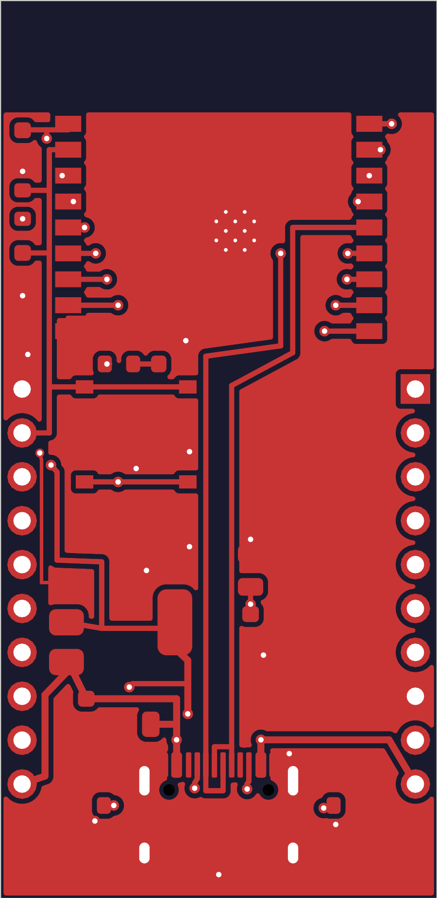
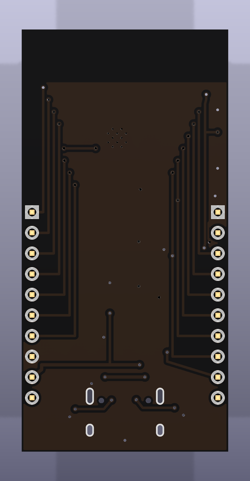
The front copper layer, exported straight from the design file. This is the actual circuit — every track drawn on purpose.